
Maintenance Tips:
Taber V5 Stiffness Tester
- Due to the sensitivity of the electronics, use a surge protector, surge suppressor or power conditioner (recommended) to filter any fluctuations in the power supply.
- To balance the pendulum, center the clamp jaws by turning the clamp screws until the clamps are aligned to the center mark. Adjust the front levelers (for the Model 150-B, adjust the tips on the front two stand legs) until the scribed line on the pendulum is directly in line with zero. The rear support is not used for leveling and should be screwed in tight.
- When testing in range 2, the roller assemblies must be inverted. For roller assemblies equipped with a sliding bottom gauge, retract the roller by turning the adjustment knob. This will allow the bottom gauge to slide down past the roller.
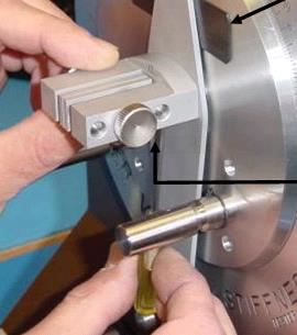
- To remove the roller assemblies, gently pull forward. Each roller assembly is mounted to a stud on the driving disc while a projecting pin on the rear of the roller assembly mates into a hole directly below (or above) each stud on the driving disc. A spring loaded plunger ball secures the roller assembly in place.
- If your readings are high (low), the gap may not be properly set between the bottom rollers. Ensure the right hand roller has been backed off 1/4 turn to set the correct spacing. This spacing is critical to allow the specimen to move freely as it is deflected. Rollers that contact the specimen or are too tight will prevent the specimen from flexing during the test.
- If your Model 150-E (or 150-D) does not automatically stop at 15° or 7.5°, return the instrument to Taber Industries for repair. This could be an indication the photoeye sensor could require adjustment or cleaning; the pendulum spacing is out of tolerance, or the encoder is no longer working properly. Note, Model 150-D encoders are obsolete and no replacement parts are available.
- For proper operation, the spacing between the driving disc and pendulum must be adjusted accurately. For instruments manufactured prior to 2011 the spacing is 0.035 inch. For instruments manufactured after 2011, the spacing is 0.010 inch. To adjust spacing, loosen the set screw located under the clamp jaw assembly on the pendulum.
- Use Taber's Calibration Specimen to verify the V5 Stiffness Tester is operating within calibrated parameters. Five different calibration specimens are available through authorized Taber distributors and are used to verify different ranges. The specimens may be returned to Taber Industries for re-certification.
- If the ratchet-stop mechanism locks up either fully open OR fully engaged, turn the adjustment knob until the mechanism moves and you are able to use the ratchet-stop knob again.
-
If the Model 150-E Stiffness tester displays 'Accumulating', stored data must be deleted. Go to the Main Menu and select "STAT". From the "Stat Menu", select "GROUP" and then select 'Delete' and then press "ESC" to return to Main Menu. To complete the data deletion, power down the unit.
